Introduction
CNC Machining / Metal Working often involves removing metal from a Part, component, or workpiece. This process is a Secondary Process preceded by a primary process, like casting, forging, welding, etc.
Machining is often required for attaining the desired dimension and Tolerances on the part to be manufactured to the design intent. this could be to achieve the FIT FORM & FUNCTION of the part in the assembly where the part is going to be used. Hence, this process of metal removal becomes an important process
This can be broadly Categoriesed into two segment
- Roughing Operation : Where major material are removed in these operation the main Objective is to remove maximum materail in minimial time . hence Metal Removal Rates (MRR) re often High
- Finishing Operation: in these operation the final shape surface finish & dimensional tolerance are achieved, due the high precision requirements of these operation often the MRR is low in these oepration
Factors to Consider
Below are some of the Factors that determine your choice of Tooling for efficient machining. Efficient machining is the key to ensure your machine shop runs optimally with out any stoppages and you are able to prodcue part that are of aceptable quality. this is Key to any CNC Machine shop to operate profitability
- Size & Shape of the work piece materal
- Material of the Workpice
- Surface Condition of the Workpiece
- Casting/ Moulding
- Forging
- Rolled/ formed
- Fabricated
- Premachined
- Hardened / Tempered
- The Machine being used
- SpindlePower
- Age/ Rigidity
- Clamping Rigidity
- Cutting Tools
- Tool Geometry
- Grade
Size and Shape of Workpiece
Size and Shape determine the overall Rigidity of the Component during the machining Proces For example
- Symetrical are more well balanced and less prone for vibration in turning operation on lathe however a slender component that is Symetrical can be a challenge .
- Component shape that are complex often more prone for unstabel clamping which can cause Vibrations
Size and shape often control the cutting condition the tools can be run at . Cutting condition need to be often adjested to ensure a more efficient Material removal & better toollife. for better productivity and effective machine untilization (OEE)
Material of WorkPiece
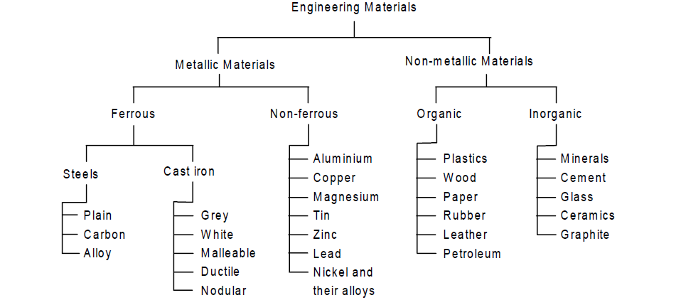
It is essential to comprehend the machinability of the material being machined to ensure that the cutting conditions and cutting tool material are appropriate for the task at hand. These materials have been broadly classified according to ISO and DIN international standards.
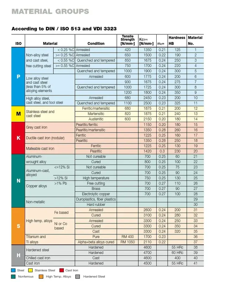
Understanding under what category your component material falls as per ISO 513 is critical to pick the right Cutting tool Material (grade) and Suitable geometry for cutting tool
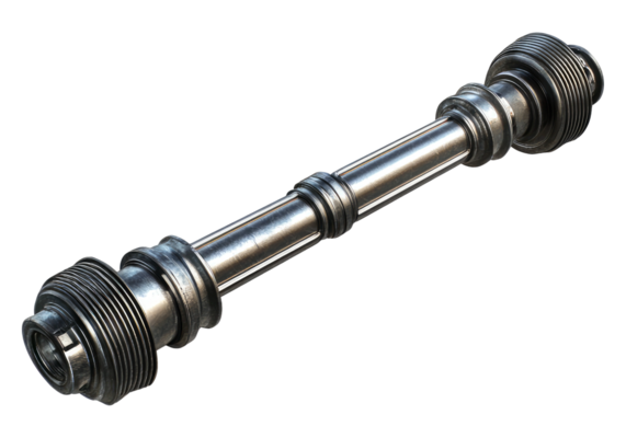
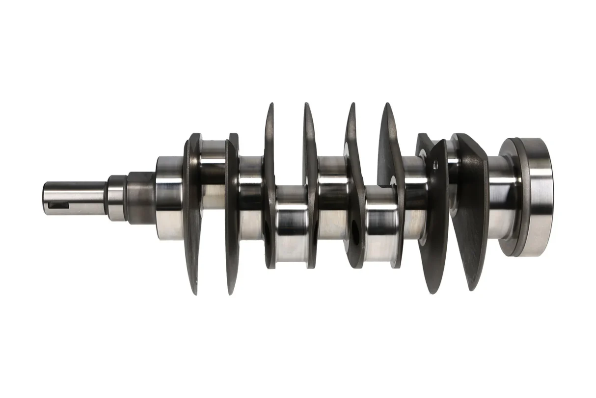
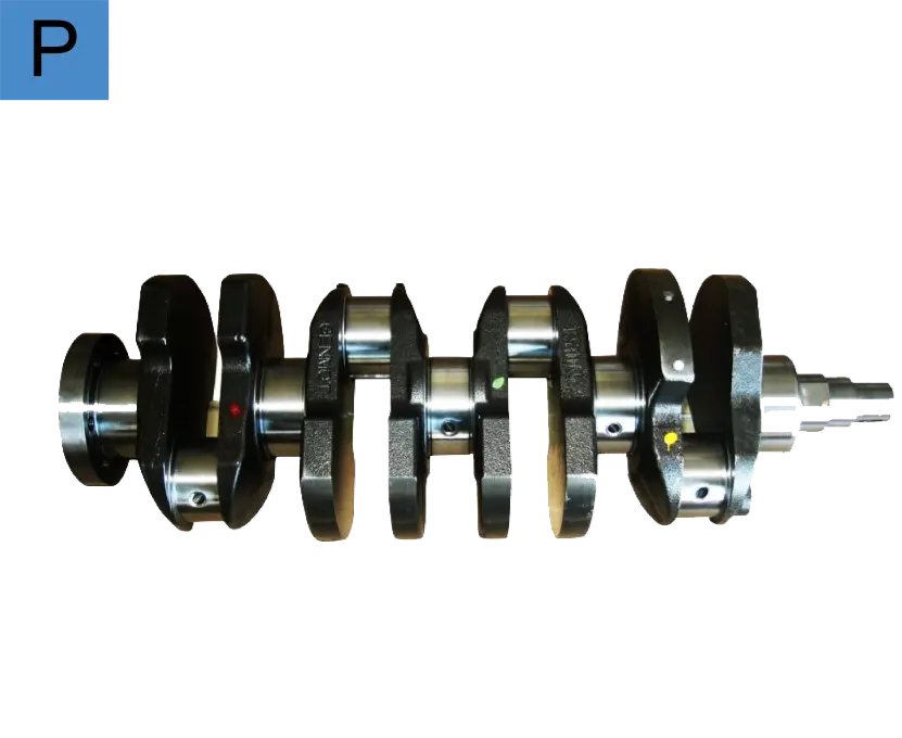
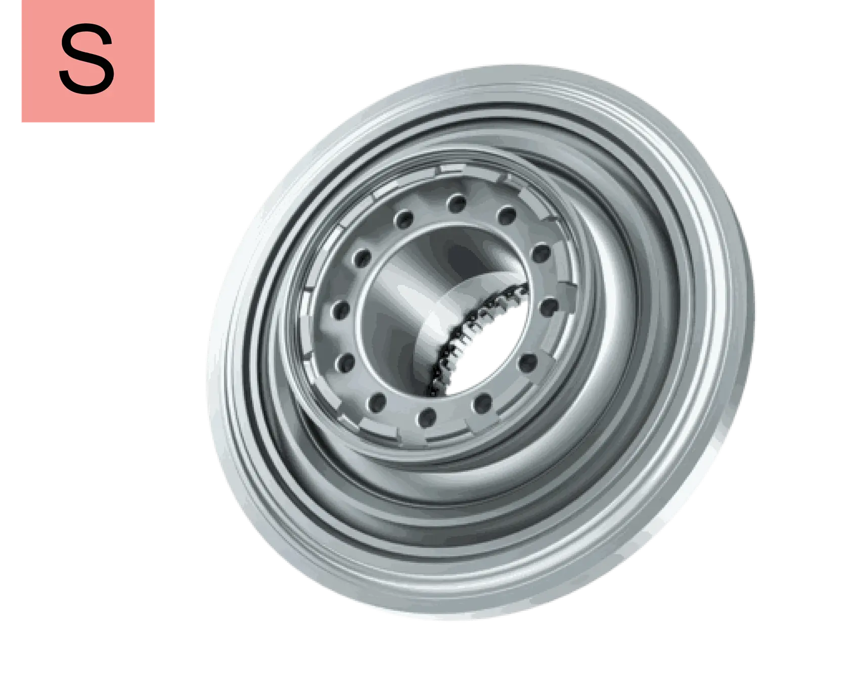
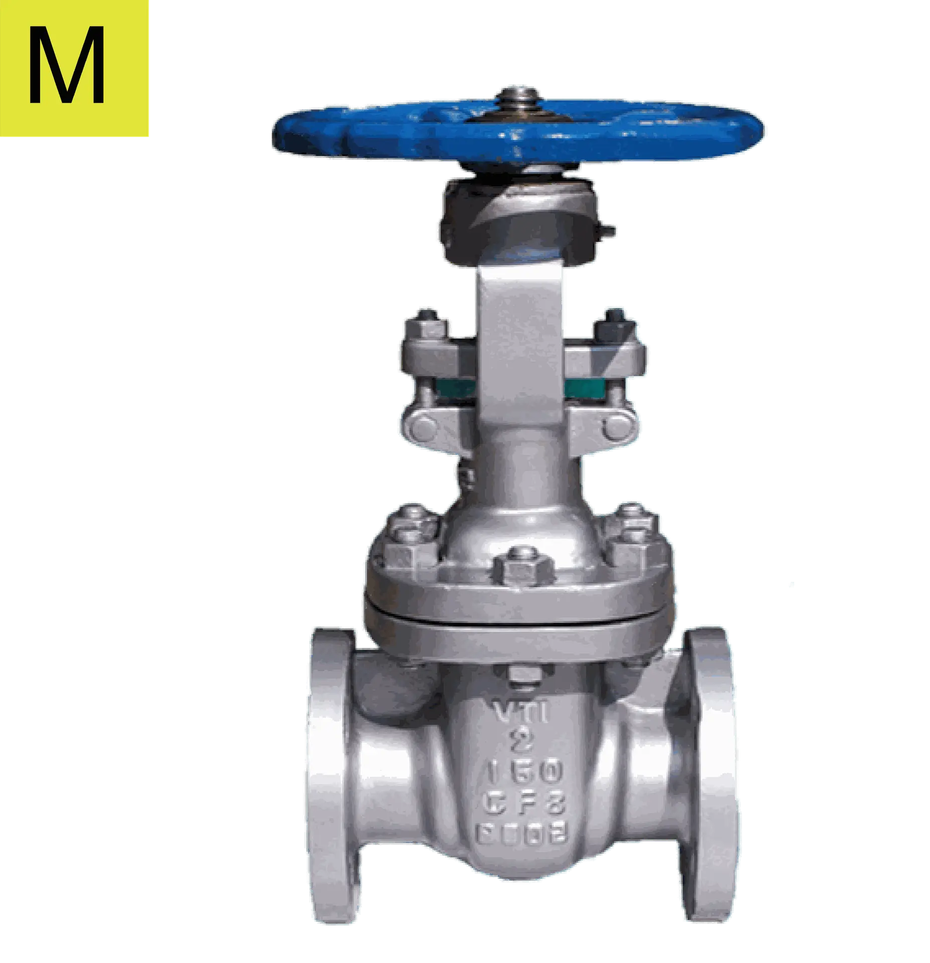
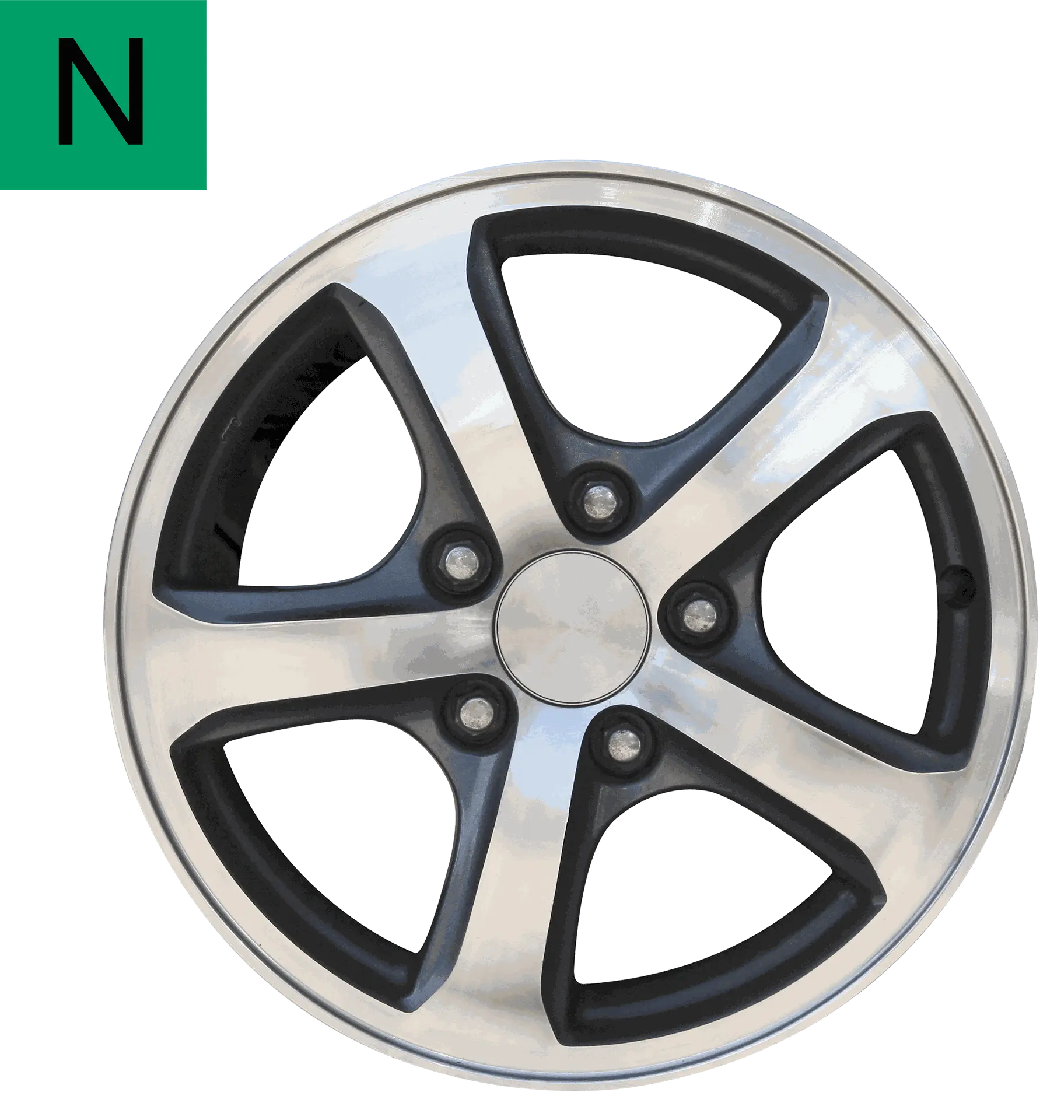
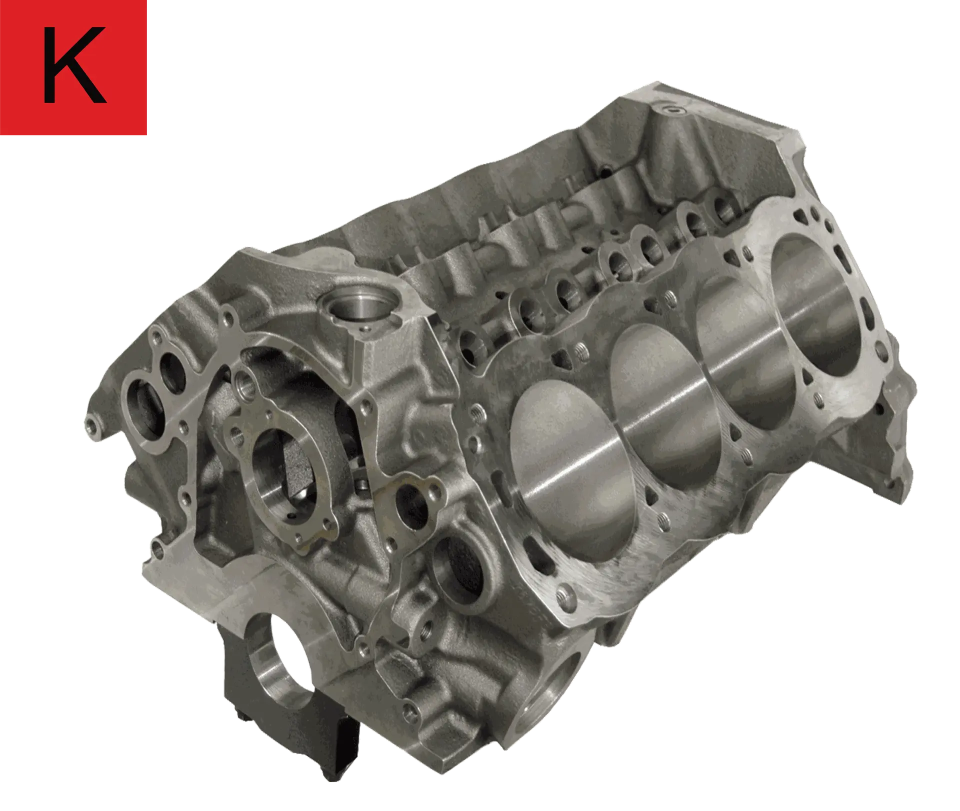
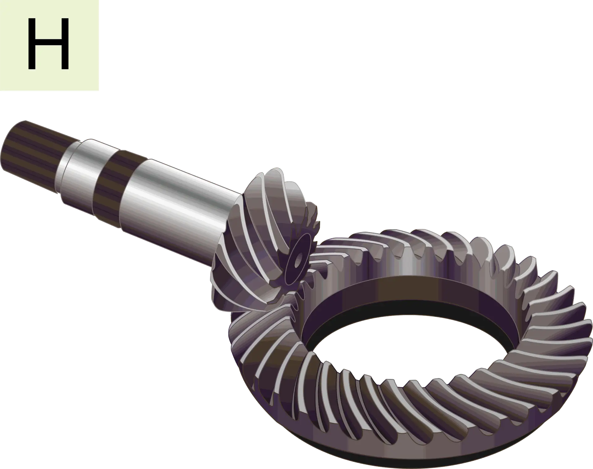
Below are some Illustrative Example of components and the broadly the category they classify under the ISO 513 Standard
Surface Condition and their Impact
Surface condition, hardness, and machinability play crucial roles in determining the appropriate tooling choices and cutting conditions we employ.
Cast or forged components often have a skin or scale layer that can be challenging to machine. To address this, tougher grades or edge conditions (such as T land or K land) are necessary to ensure that the tool can endure the demanding cutting circumstances required to remove material effectively.
Similarly, harder materials require a stronger cutting edge to guarantee that the carbide remains more wear-resistant than the material being machined
Machine conditions and Clamping Rigidity
Often overlooked, optimising cutting conditions is crucial in the machining process. Numerous factors influence and need careful consideration, such as the age and condition of the equipment being used, spindle power, type of drive delivering power to the cutting tools, and the type of machine itself.
- Vertical Machining Centre (VMC): The VMC configuration is typically preferred for precision machining due to its rigidity. It is often chosen for small to medium part machining.
- Horizontal Machining Centre (HMC): The HMC configuration is ideal for medium to large components, which are mounted on a rotary table or tombstone configuration. Due to their relatively large size, ensuring clamping rigidity is essential to achieve vibration-free machining.
- Tool Overhang: It is always desirable to have an optimal tool overhang to get the job done effectively. Excessive overhang can result in unstable machining conditions and limit cutting performance.
- Spindle Connection: Several types of spindle connections link the spindle to cutting tools. Minimal connection is often preferred, and modern CNC machines feature various spindle tapers.
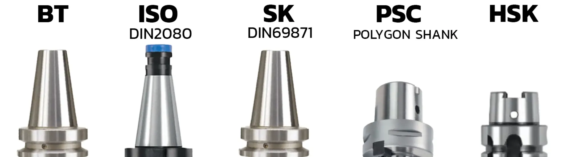
- BT (BT MAS) tool holders are used on Japanese, Korean, Taiwanese, and American machine centres.
- SK (DIN69871) tapers are for German, European, and some American machining centres with CAT40/CAT50 tooling.
- ISO (DIN2080) tool holders suit conventional milling machines with manual or automatic draw bars.
- HSK (DIN69873) tool holders are designed for high-speed CNC machining centres with spindle speeds above 10,000 RPM. Developed in Germany, HSK tapers excel in high-speed applications due to their hollow shank design for better power transmission, accuracy, and stability. These Taper are short taper(7:24) and have taper and Face Contact and for the more stable connection bettwen the Spindle and the cuttign tool offering good rigidity in high speed and Feed applciations
- KM™ Connection this again short Taper connection largly popular for Quick change solution on lathe machine this connection offer the Taper and Face contact
- PSC ( ISO 13399 ) the PSC Connection also populary know as the Capto Connection is a Unique Polygon shaped shortaper. this unique design has better taper contact due the unique Poygon shape which provide excellent torque transmission and rigidity under under high spindle RPM
Cutting Tools
Cutting Tools are often the last interface between the machine Spindle and the workpiece or the material machined . Modern Day cutting tools are made from advance manufacturing technology and variety of material starting from tool Steel to advance material liek Ceramics CBN( Cubic Boron Notride) and Poly Crytalline Diamond (PCD)
Important Factors that influence the performance of these cutting tools are
- The material they are made
Choosing the right cutting tool material depends on the material to be machined. The cutting tool must be harder than the workpiece. Modern machining processes have advanced from working with steel to handling hard materials like super alloys and white cast iron, which are abrasive. Understanding the appropriate cutting tool material is crucial.
Harder workpieces require cutting tools with hot hardness, a key metallurgical property. Hot hardness refers to a material's ability to maintain its shape, geometry, and strength at high/ elevated temperatures, essential for cutting tools exposed to extreme conditions during machining.

- The tool geometry
A Basic Cutting tool Geometry consist of the following the
a :Rake angle
Angle formed between the rake face of the cutting wedge & and the line perpendicular to the work piece
c: Clearance angle
Angle formed between the flank face of the wedge & surface of the machined work piece
b: Wedge Angle
Angle formed between the rake face of the cutting tool and the flank of the cutting tool this is angle
NOTE:
a+b+c= Will always be 90°
- For cutting soft & Gummy material: Angle B(Wedge Angle)=40°~50°, such as aluminum, Copper, Silver etc
- For cutting ductile metals: Angle B(Wedge angle)=55°~75°, such as 42 steel.
- For cutting hard and brittle metals:Angle B(Wedge angle)=75°~85°, Cast Iron, Hardened Steel/ High strength Material
d: Interference / Depth of cut

Influence of rake angle
- Facilitates the easy flow of the chip from the shear zone this ensure lesser obstruction to the chip flow and reduces Work done at the zone of cut thereby reducing power consumed
Types of Rake Angle
Zero Rake
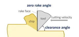
- Provides Good in cutting edge strength but may cause chip evacuation issue causing premature tool wear
- However nay not be the best condition for optimal tool life as we we may have chip evacuation issues
Negative (-ve) Rake
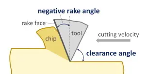
- Higher Cutting forces
- Stronger cutting edge
- Recomended for Unstable cutting condition . higher material removal rates or harder material surfaces
- first choice for hard material and soft chipping material such as Cast iron
Postive( +ve) Rake
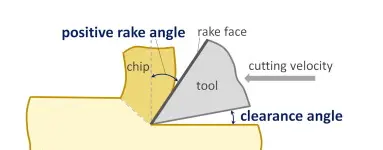
- Lesser Cutting forces
- Weaker Cutting Edge
- Recomended for stable cutting condition and good surface finish and for dimesnional control
- first choice for soft and Gummy material and material which has tendency to work harden
Cutting Conditionscutting conditions they are being used at
- Cutting Speed
- Speed
- Depth of Cut